Devising Methods for Signal Connectors and Cable Layout to Ensure Signal Quality
In the world of electronic systems, ensuring signal integrity is paramount for reliable data transmission and efficient power delivery. Keven Coates, Senior Electrical Engineer at Fluidity Technologies, emphasizes the importance of this aspect, particularly in high-speed and sensitive systems.
The Controlled Impedance Design Guide, a comprehensive resource developed by Fluidity Technologies, outlines best practices for achieving signal integrity with cables and connectors. This guide spans across 6 chapters, 56 pages, and is a 60-minute read. It covers topics such as understanding why controlled impedance is necessary, stack-up design guidelines, how to design for impedance, common mistakes to avoid, and more.
Best Practices for Achieving Signal Integrity
To maintain signal integrity, several key practices should be followed.
- Minimize Crosstalk: Sufficient spacing between traces or wires is essential to prevent signals from adjacent lines interfering with each other. For USB signals, at least 3 times the trace width should be maintained.
- Control Reflections and Impedance Matching: Use termination resistors when needed to match impedance at the ends of transmission lines to prevent signal reflections that degrade quality. Keep connector and cable impedance consistent to avoid discontinuities.
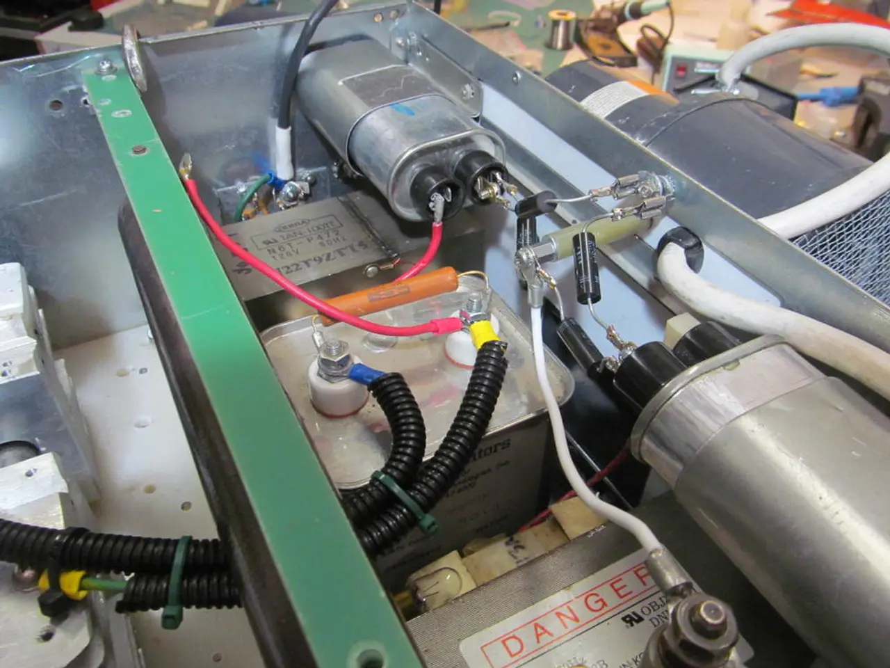
- Reduce Electromagnetic Interference (EMI): Employ shielding techniques such as shielded twisted pair (STP) cables, grounding connector shells, and adding ground vias around signal paths to minimize noise pickup and interferences.
- Use High-Quality Connectors and Proper Mechanical Design: Match connectors electrically to wire gauge, use strain reliefs to protect solder joints and ensure mechanical stability, and protect connectors from environmental factors like dust and humidity with sealing or potting when relevant.
- Optimize PCB-to-Harness Transitions: Keep traces short and wide for current paths, maintain consistent impedance, and control trace geometry to lower resistance and ensure stable signal and power delivery.
- Simulation and Testing: Utilize signal integrity simulation tools and post-manufacturing methods like eye diagram analysis to verify and optimize signal quality, checking parameters such as jitter and bit error rates.
- Limit Cable Length: Keep cable lengths within recommended distances (such as under 100 meters for Ethernet) to avoid attenuation and signal degradation that reduces performance. For longer distances, use repeaters or switches to preserve integrity.
- Minimize Connectors and Joints: Each connection introduces resistance and possible signal loss, so keep these minimal and ensure they are secure and well-made.
Understanding Energy Flow in Wiring Circuits
Energy does not primarily flow inside the metal conductors (wires) themselves but rather in the electromagnetic field around and within the conductor environment. Electrical energy propagates via the electromagnetic field established by voltage and current in the conductors. This is why controlling impedance, minimizing reflections, and reducing electromagnetic interference are critical for signal integrity—because disturbances affect this energy flow path.
In summary, maintaining signal integrity requires comprehensive attention to electrical characteristics (impedance, reflections), mechanical design (strain relief, environmental protections), and testing (simulation, measurements), coupled with managing cable length and shielding to safeguard the electromagnetic energy flow within wiring circuits. This holistic approach maximizes data reliability and power delivery efficiency in high-speed and sensitive electronic systems.
Keven Coates and his team at Fluidity Technologies are available to assist with any queries on employing cables and connectors in your design to enhance signal integrity. They recommend consulting the Controlled Impedance Design Guide for guidance on employing cables and connectors in your design to enhance signal integrity.
[1] Source: IEEE Std 100-2019, IEEE Standard Dictionary of Electrical and Electronics Terms [2] Source: Hiroshi Kuwabara, "Signal Integrity and Power Integrity in High-Speed Digital Design," Artech House, 2004. [3] Source: Robert J. Tillman, "High-Speed Digital Design: A Handbook of Black Magic," McGraw-Hill, 2001. [4] Source: John D. Cressler, "High-Speed Digital Design: A System Approach," Prentice Hall, 2002.
Data-and-cloud-computing technologies have increasingly relied on the principles of controlled impedance to ensure reliable signal transmission and power delivery in high-speed and sensitive systems, as outlined by Keven Coates, Senior Electrical Engineer at Fluidity Technologies. The Controlled Impedance Design Guide, developed by Fluidity Technologies, presents best practices to achieve signal integrity using cables and connectors, covering topics like controlled impedance design, impedance matching, and reducing electromagnetic interference.


